
Horizontal Fluidized Bed Dryer
Key words
Category
Enquiry
Parameter download


 Horizontal Fluidized Bed Dryer
Horizontal Fluidized Bed Dryer
Horizontal Fluidized Bed Dryer
Horizontal Fluidized Bed Dryer
Horizontal Fluidized Bed Dryer
Horizontal Fluidized Bed Dryer
Horizontal Fluidized Bed Dryer
Principle
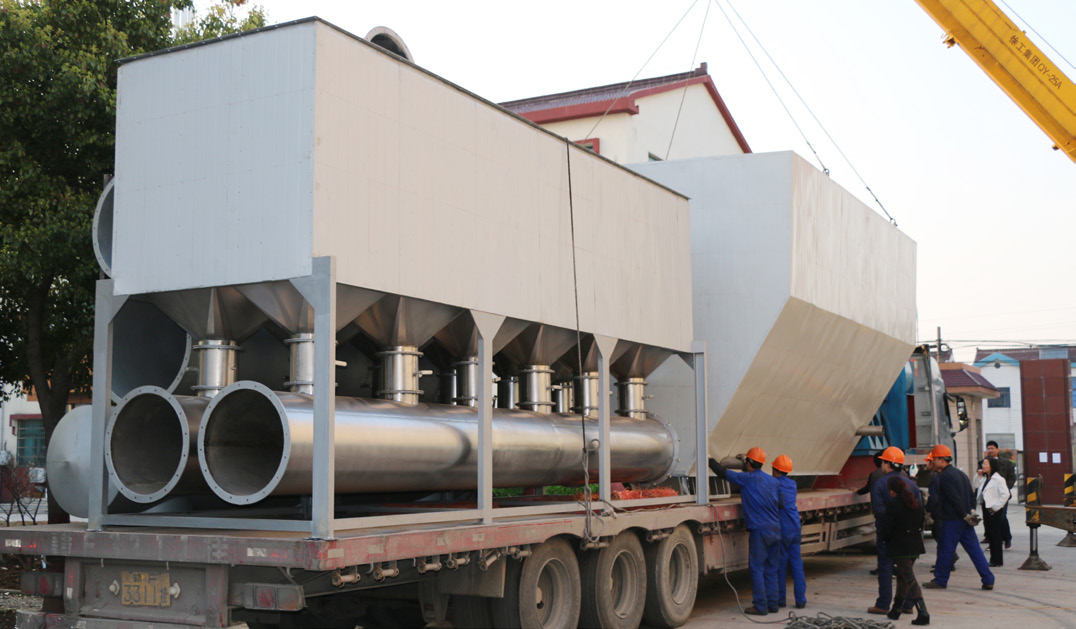
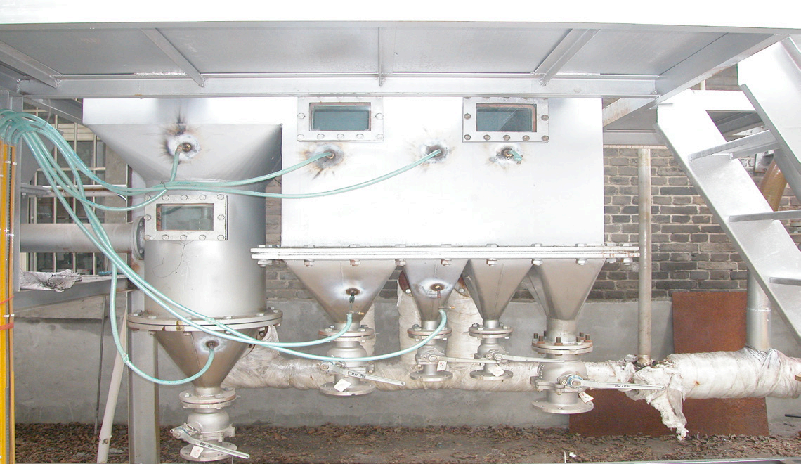
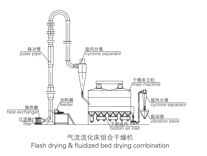
◆After the filtered air is heated, it enters the fluidized bed through the air distributing valve. The wet material from the Quantitative feeder is blown upwards by the high-pressure hot air and it will reach the boiling state. Due to the extensive contact between the hot air and the material, the process of heat and mass transfer is enhanced, so that the drying process can be completed within a relatively shortamount of time. The material enters the system from the inlet of the bed, and after a few seconds or a few hours of fluidized drying, it flows out of the system from the outlet located at the other end of the bed automatically or in batches. The operation of this eeuipment is generally under negative pressure.
Features
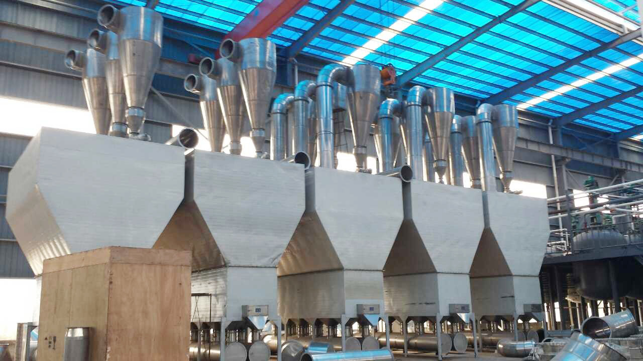
◆The processing capacity of the equipment is large, and the discharge volume is also large. The dust is collected through a built-in cloth bag or an external dust collector.
◆The retention time and the temperature of the material inside the dryer can be adjusted.
◆The structure of the equipment is simple; the maintenance is convenient; the temperature of the bed is uniform.
◆The operation of the equipment can be continuous, semi-continuous or intermittent.
◆This equipment is suitable for drying powdery and granular materials with good fluidity. For materials with high moisture content and high cohesiveness, a pretreatment step is necessary before the drying process.
◆The structure of the mesh can be adjusted according to the requirements. The thickness of the material layer can be adjusted by the overflow plate.
◆A cooling section can be added to the bed surface before the material is discharged, so that thematerial can be packed directly after being cooled.
Applications
◆For drying medicines, chemical materials, and food; for materials with particle sizes around 0.1- 6mm; optimal particle size is 0.5- 3mm.
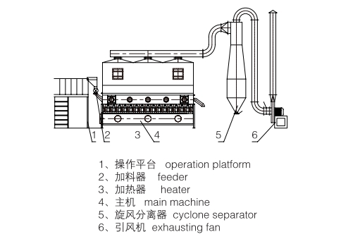
Stucture Diagram

Technical Specifications
| Model | Capacity (kg/h) | Power of Fan (kW) | Temperature of Inlet Air (℃ ) | Feeding Method |
| XF10 | 10-15 | 7.5 | 60-200 |
1 . Feeding method is determined separately. 2.The amount of water evaporated depends on the characteristics of the material. 3.The configuration data are for reference only. |
| XF20 | 20-25 | 11 | 60-200 | |
| XF30 | 30-40 | 18.5 | 60-200 | |
| XF50 | 50-80 | 30 | 60-200 | |
| XF1x6 | ~200 | 60 | 150 | |
| XF2x12 | ~1200 | 230 | 150 |
Related Equipment
Leave your needs behind
We will contact you within one working day. Please pay attention to your email.

DO YOU HAVE QUESTIONS?
We will contact you within one working day. Please pay attention to your email.
CONTACT US

Address
501 Changhe Road, Zhenglu Town, Changzhou City, Jiangsu Province, China (ZIP Code: 213115)